
 |
| Baofeng DM-1801 with interface |
The popularity of AFSK Digital Modes coupled with the ability to encode/decode with an average computer has made soundcard interfaces a popular accessory for Amateur Radio operators.
When I first got into Digital Modes I wanted to experience the "quick win" and "taste of success" so I opted for an off-the-shelf passive sound card interface. I went with the West Mountain Radio RIGBlaster Nomic which I still have to this day. You sometimes find used ones for $20 USD at Hamfests.
 |
| Passive Sound Interface |
Another popular off-the-shelf interface is the Tigertronic Signalink USB. The Signalink's advantage is rather than a passive audio isolation interface with a serial circuit for keying a transmitter (PTT), it connects as a USB Sound card with an internal PTT circuit triggered by the transit audio. Having a second sound port is useful to keep system sounds from keying up the transmitter.
 |
| Appears as a USB Sound card |
While both products have simple connectivity to your computer, both need to accommodate the variety of radio connections across make and model. This requires custom cables and connectors provided by those manufacturers.
While there are a number of soundcard interfaces you can buy, building one is a good first amateur radio project that is simple and useful. In this article we will review the fundamentals of a basic sound interface circuit and then build our own sound card interface.
Basic Sound Interface Circuit
The core circuit design for most interfaces is depicted below.
 |
| Basic Sound card interface Circuit |
There are two identical circuits providing a path for audio in each direction. All that is being provided by these circuits is audio isolation between the radio audio and the computer audio. Simple circuits using a transformer, resistor, and capacitor
The bottom circuit is the PTT (Push-to-Talk) circuit. RS-232 Serial ports have been used for ages for keying a transmitter using the RTS and DTR signals. That is why you will see RTS and DTR commonly referenced in PTT circuits.
You can get away without using PTT and use for VOX settings on your radio for connection-less modes like APRS and many of the popular HF digital modes. But the delays VOX introduces from receive to transmit are insufficient for connection-oriented modes like connecting to Packet BBS where timing is critical.
A Sound Card Interface Build
We will build a sound card interface for handheld radios that use a K2 connector, This includes Kenwood, Anytone, Wouxun, and Baofeng radios. We will start with the core circuit design that is available in kit form from Easy Digi.
To isolate system sounds from our digital mode sounds we will include a USB sound dongle between the interface and the computer. PTT circuits for sound card interfaces have a heritage of using the serial port on a computer. Since newer laptops no longer have serial ports, we will use a USB-to Serial adapter for the PTT circuit on the interface board to connect to.
Our component list looks like this:
- Easy Digi PCB Kit
- 3.5mm TRRS USB Sound Adapter
- 3.5MM TRRS Male connect with pigtail
- USB-to-Serial AdapterInterface
- K2 Connector Pigtail
Easy Digi PCB Kit
The Easy Digi PCB Kit will be the foundation of our build providing the core circuit.
 |
| Easy Digi Kit |
3.5mm TRRS USB Sound Adapter and Pigtail
To reduce the number of cables we will go with 3.5mm TRRS.
 |
| 3.5mm TRRS USB Sound Adapter |
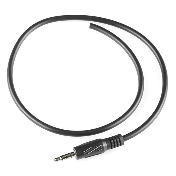 |
| 3.5mm TRRS pigtail |
USB-to-Serial Adapter
It is rare for a desktop or laptop computer to include a serial port. The USB-to-Serial adapter supplants this and is used solely for the PTT circuit. When purchasing a USB-to-Serial adapter/cable ensure it includes ALL serial connection signals since the only signals we will use in this connection are DTR, RTS, and GND.
K2 Connector Pigtail to Radio
The K2 Connector with pigtails can be found as "2 Pin 4 Wire Speaker Mic Cable Line For Baofeng UV5R Kenwood TK370 Motorola" on Amazon or cheaper in bulk on eBay.
Build the Easy Digi PCB kit using the instructions provided.
 |
| K2 Connector with pigtail |
Building the Interface
Build the Easy Digi PCB kit using the instructions provided.
 |
| All PCB components mounted. Last leads to be trimmed |
Find a case for the kit and drill three holes for the cables.
 |
| Nylon stand offs added to support PCB |
A cheap way I prevent the holes from cutting through the cables is to use electrical tape on the inside and outside surfaces of the case over the holes. Drill two mounting holes in the case to support the PCB using nylon standoffs.
All we need is a single channel of audio from the computer. Left is typically used with right audio channel historically reserved for tone-based keying. So when connect the 3.5mm TRRS pigtail to the PCB as depicted below, we will not connect to right channel.
 |
| Top view of PCB and connections |
To utilize the PTT circuit with radios that use K2 connectors, you will need to add two jumper wires to the PCB. One end of each jumper will be shared with K2 pigtail connections that need to connect to RX AUDIO and MIC GND as well.
 |
| Graphic courtesy of miklor.com |
Take the K2 pigtail and match the tip, ring, and sleeves to the corresponding wires. Once verified, solder the Baofeng speaker/mic cable to the board as follows:
- SPK- to RX GND (hole just above RX AUDIO)
- MIC+ to MIC IN
 |
| Yellow lines show the two jumper wires to be added |
Create the two jumper wires as follows:
- Wrap SPK+ and PTT GND together and solder to RX AUDIO
- Wrap MIC- and PTT HI together and solder to MIC GND
 |
| Serial Connections |
Testing the Interface
Best to test the audio and PTT circuits separately. For the audio test you can try with an APRS application with your radio set for VOX to ensure both audio circuits work. Testing the PTT circuit can be tricky depending on:
- Operating System
- USB-to-Serial driver settings
- Ham Radio Application PTT settings.
Be thorough in document the configurations of each as you perform your testing and getting the various applications you have to work with PTT.
 |
| Completed Kit. Using just GND and DTR for PTT Circuit to USB Serial Adapter |
I made a picture album of the build process for those interested.
Best of Most Worlds
The most time consuming part for me when it comes to experimenting with digital modes across different radios is interfacing them. That is why I keep a small stock of the Easy Digi PCB kits to build for each radio type even if I know the setup will not be permanent. With most of my projects using Raspberry Pi as the compute, using GPIO pins for PTT is more efficient than the overhead of USB and Serial.
In a future article we will explore designing and building our own interface using the Open Source KiCad EDA to design the PCB and PCB fabrication services. The interface will include the following;
- Single USB connection for Audio and PTT (optional)
- Includes USB audio
- Easily reconfigurable for different radios
- Supports PTT triggering using 3.3VDC to 12VDC or USB
Happy New Year !
- Joe. NE2Z
can you expand on the usb-to-serial connection. In the drawing on the main page you show three connections. In the pictures you posted there are only two wires shown in the connection?
ReplyDeleteI think he says he only needed the DTR and ground wires to get the PTT function to work...
ReplyDeleteThanks. I thought that might be the case, but wanted to check.
ReplyDeleteBe advised the Miklor diagram shows that the Mic - (or PTT) has to be connected to the SPKR- (PTT GND) to trigger PTT in the Baofeng - but his instructions say to "Wrap SPKR+ and PTT GND together" for the first jumper.. So, when that didn't work as shown for me, I wrapped SPRK- and PTT GND together, which worked.
ReplyDeleteCan you show diagram/pics of the Pi GPIO connections please.
ReplyDeleteThe jumper in the drawing from from PTT Gnd to Audio Rx + seems incorrect. Shouldn't it be PTT Gnd to 2.5 mm Audio Rx - sleeve? The hole above next to the resistor R3.
ReplyDeleteNever mind. I wired per the instructions here and is working find. I had other problems that I finally resolved, but the PTT jumpers described here are good.
Delete